


1. INTRODUCTION
Ti and Ti alloys are high-temperature and light-weight metals with excellent properties, such as high strength, toughness, high degree of corrosion resistance, and biocompatibility. Owing to these characteristics, Ti and Ti alloys are used for light-weight components not only in the aerospace industry, but also in high performance applications, such as automobiles and implants [1-4]. However, the production of Ti-components entails high cost because of the metalŌĆÖs high reactivity with oxygen and atmospheric gases [5]. Since Ti has a particularly high oxygen affinity, the manufacturing process requires considerable amounts of energy, and results in large quantities of scrap. This consequently raises the price of Ti products. Therefore, a large number of researches studies have been conducted on the recycling of Ti scraps [6-9].
Recently, a method for utilizing recycled Ti as a raw material for ferrotitanium has emerged. Ferrotitanium is widely used in hydrogen storage alloys, the aviation industry, and as a deoxidizer for steel manufacturing [10-12]. In particular, the Ti-based deoxidizer has high reactivity with carbon, oxygen, nitrogen, and sulfur during the steelmaking process. This is beneficial as the Ti deoxidizer can prevent chromium depletion by carbon, which has a tendency to absorb chromium in the temperature range of 400 to 900 ┬░C, forming Cr23C6 [12]. Furthermore, Ti scraps are the preferred raw material for producing Ti deoxidizer because they are available at a significantly lower price point than other highgrade rutile ores or high Ti soils [6].
Ti scraps generated during the machining process are contaminated by cutting oil. Cutting oil provides cooling and lubrication properties. However, the used cutting oil accumulates physical and chemical contaminants, losing it properties and becoming contaminated, producing toxic waste [13-17]. Therefore, raw scraps have a harmful effect on the product. When using Ti scraps to obtain a Ti alloy with desired characteristics, a pretreatment process to remove the cutting oil is required.
W2 types of water-soluble cutting oil are mainly used for titanium cutting. Since the surface temperature of the cutting process is not high enough to form TiC, the remained cutting oil on the surface is retained during recycling, and has a greater effect on product properties. If the oil on the surface of the Ti scraps is not completely removed, it becomes a major source of gaseous impurities during melting and recycling. In particular, the adhered oil remains as carbon impurities in the molten metal during the subsequent melting process. An acidic solution or organic solvent is generally used to remove not only the oil, but also the oxygen layer. In addition, this also improves porosity [18-22]. However, this process may pose problems to the environment and process safety.
To address this issue, a relatively eco-friendly alkaline degreasing solution, such as an aqueous solution based on NaOH, is used [23,24]. Alkaline degreasing mainly involves a saponification reaction between the oil and the aqueous alkaline solution. Saponifiable fats react with the aqueous alkaline solution, dividing it into saponin and glycerin, which are sodium fatty acids. Saponins are subjected to emulsification and dispersion by the aqueous alkaline solution.
In our previous study [25], Ti turning scraps were immersed in an alkaline solution to avoid the use of an acidic solution. However, the concentration of the alkaline solution had to be very high. Hence, in this study, to reduce the concentration of the solution, we conducted ultrasonic cleaning of the Ti scraps immersed in an alkaline solution. The optimization of the alkaline degreasing solution for ultrasonic cleaning of the contaminated Ti turning scraps was carried out. Subsequently, we also investigated the effect of the ultrasonic cleaning process on the preparation of ferrotitanium ingots using the pre-treated Ti turning scraps.
2. EXPERIMENTAL PROCEDURES
The overall flow of the experiments is shown in Fig 1. The solution for the pre-treatment of Ti scraps was primarily composed of NaOH or tetrasodium pyrophosphate (TSPP; Na4P2O7) based on a previous study [25]. However, to pretreat Ti scraps in lower concentrations of the solution, ultrasonic cleaning was adopted, which demonstrated good efficiency in cleaning [26]. Ultrasonic cleaning creates shock waves by forming micropores in the solution and its cleaning effect is based on creating random or irregular agitation in the solution. To remove the oil adhering to the surface of the Ti scraps, they were immersed in the alkaline solution, washed with an ultrasonic cleaner at 40 kHz for 10 min, and then rinsed. The washed scraps were dried at 70 ┬░C for 2 hr in a vacuum oven to produce pre-treated scraps. An industrial digital camera (SKT ML500C-125A) was used to photograph the contact angle. The pH of the solution before and after washing was measured by a pH meter (Mettler Toledo, Five Easy Plus. Carbon, oxygen, and nitrogen analyses (Eltra CS-2000, ON-900) were performed to determine the concentration of gas impurities in the Ti scraps.
Next, ferrotitanium ingots were prepared by melting the pre-treated Ti scraps along with electrolytic iron at a mass ratio of 7:3. Twenty-one g of Ti and nine g of Fe were pressed under 45 MPa pressure in a compaction mold with a diameter of 30 mm, to form a green compact. Thirty g of this green compact was placed on a water-cooled copper mold in a chamber, and the chamber was evacuated to an air pressure of 5.5 ├Ś 10-3 torr. Next, ultra-high-purity argon (99.999%) was added to the chamber to bring its pressure back to atmospheric pressure. Then, the green compact was premelted by an electrical discharge at an output of 5 kW. The ferrotitanium ingots were prepared using two methods, vacuum arc melting (VAM) and plasma arc melting (PAM). The melting times with these two methods were 10 and 20 min, respectively. X-ray diffraction (XRD) analysis of the ferrotitanium ingots was performed (SHIMAZU, LabX XRD-6100, 40 kV, 30 mA, Cu-Ka radiation). After etching for 3 seconds in a solution (water : nitric acid : hydrofluoric acid = 97 : 2 : 1), scanning electron microscopy (SEM) and energy dispersive X-ray spectroscopy (EDS) were used to observe the surface of the ingots and analyze their microstructure.
3. RESULTS AND DISCUSSION
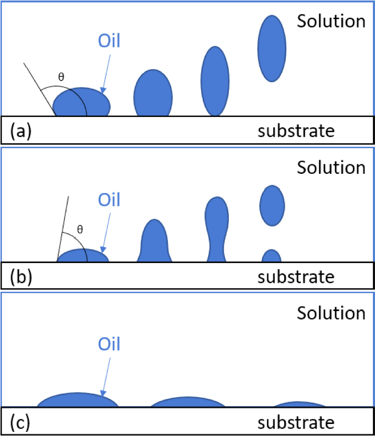
There have been many reports on the subject of cleaning oil contaminants [27-29]. Categories of oil washing can be classified into roll-up, emulsification, and solubilization mechanisms. Depending on the interaction between the solution, oil, and substrate, the contact angle and mechanism are different, and can be expressed through the following equation.
where ╬│ow is the interfacial tension between the solution and the oil; ╬│os is the interfacial tension between the oil and the substrate; ╬│ws is the interfacial tension between the solution and the substrate, and ╬Ė is the contact angle. When ╬│os is greater than ╬│ws, ╬Ė will be greater than 90 o. Under these conditions, the roll-up mechanism is easy to operate. In this mechanism, the solution wets the substrate and removes the oil. A schematic diagram of the roll-up mechanism is shown in Fig 2(a).
On the other hand, when ╬│ws is greater than ╬│os, ╬Ė will be smaller than 90 o, and the emulsification mechanism is more effective. Here, the oil is not completely removed, and necking occurs as shown in Fig 2(b). Finally, the third mechanism, namely direct solubilization, shown in Fig 2(c), can operate when there is enough surfactant in the solution [28].
There is, however, another mechanism for forming an intermediate phase at the interface between the solution and the oil. This mechanism operates when the oil contains a lot of polar components. When the liquid crystals have grown sufficiently through the interaction of polar oil with the adsorbed surfactant, the intermediate phase is decomposed by stirring and falls off into solution.
According to an earlier study on the cleaning of oils on substrates [27], the contact angle and wettability of the oil depend on the pH of the solution, and the Ti scraps tend to be washed well at a pH of 9.5ŌłÆ10.5 [29]. The compositions of the pre-treatment solutions considered in this study (designated as PT-1 through PT-5), in the above-mentioned pH range, are shown in Table 1. TSPP is a representative component used as soap builder and has the appropriate pH and oil removal effect when washing cotton fabrics. Also, pyrophosphate gives greater lathering effect [31,32]. In previous studies, cleaning was carried out at a relatively high concentration to remove the oil from Ti scraps [25]. However, through a salting-out effect on the soap, hydroxyl ions reduce the surface activity [31]. To improve this, variables were applied to the NaOH and TSPP concentration. Here, the concentrations of PT-1 and PT-4 were adjusted using NaOH, while those of PT-2, PT-3, and PT-6 were adjusted using TSPP. PT-5 consists of NaOH and TSPP. In addition, to study the effect of ultrasonic cleaning, PT-6 had the same composition as PT-2, but without ultrasonic cleaning.
The degreasing in an alkaline aqueous solution during the pre-treatment can be represented by the following equation.
From the chemical equation, it is seen that the higher the NaOH concentration, the better the reaction is, because NaOH is the main source of the reaction. In a previous report pertaining to immersion washing [25], it was observed that the degree of washing increased as the concentration was increased up to 2M NaOH. However, during the pretreatment using ultrasonic cleaning, the solution containing large amounts of NaOH tended to wash the Ti scraps to a lesser extent.
Comparing the amount of C remaining in PT-1 and PT-4 in Table 2, it can be seen that PT-4, which has a higher NaOH concentration was washed less than PT-1. However, it may be also observed that the reaction of NaOH was not the main mechanism of washing. On the contrary, the washing was predominantly a function of the contact angle and the wettability, which were in turn, affected by the pH [27]. Thus, if the pH is very high, then the contact angle becomes small, and hence, it can be inferred that the oil remains on the substrate by the emulsification mechanism, and not the roll-up mechanism. PT-2, PT-3, and PT-6, which were composed of TSPP, showed lesser change in pH after washing compared to PT-1, which was composed of NaOH. They confirmed that the cavitation from ultrasonic affected the results.
In the case of PT-1 and PT-4, NaOH reacted with the oil, resulting in a lower pH. But in the case of PT-4, there was very little pH change because the NaOH concentration was too high. On the other hand, in the case of PT-2 and PT-3, Na+ in TSPP was dissociated, adjusting the pH to a proper level, and also acted as a buffer, which suppressed the change in the pH value. Compared to PT-2, PT-5 had more carbon left. This shows that pH, even in the presence of TSPP, affected the contact angle and surface activity.
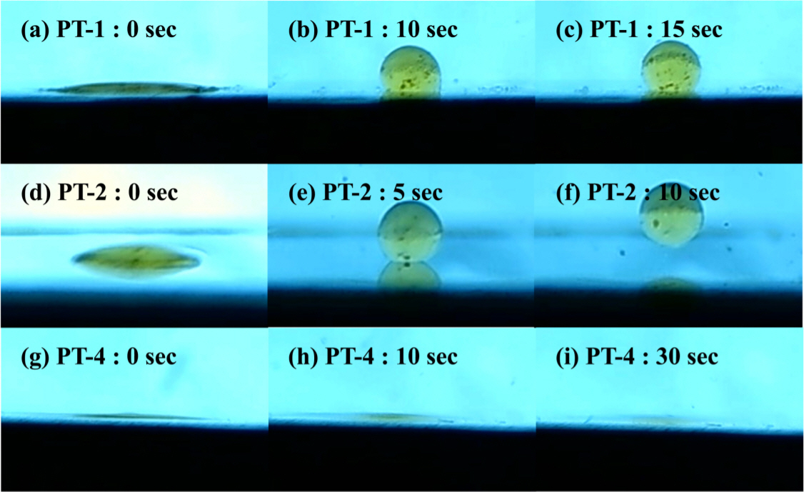
Figure 3 is an image taken over time after sessile drop, used to observe the contact angle. The substrate was prepared by polishing after melting the Ti scraps, and the oil was obtained from the surface of the Ti scraps. Figure 3(a)~(c) and (g)~(i) are solutions consisting only of NaOH. In the case of PT-1, oil was spheroidized over 15 seconds by increasing the contact angle, and there was no significant change afterwards. On the other hand, with PT-4 the contact angle became smaller and oil wet. It was confirmed that this difference in contact angle was due to the pH value. In the compositions PT-2 and PT-3 containing TSPP, the oil was spheroidized and then fell off as in Fig 3(d)~(f).
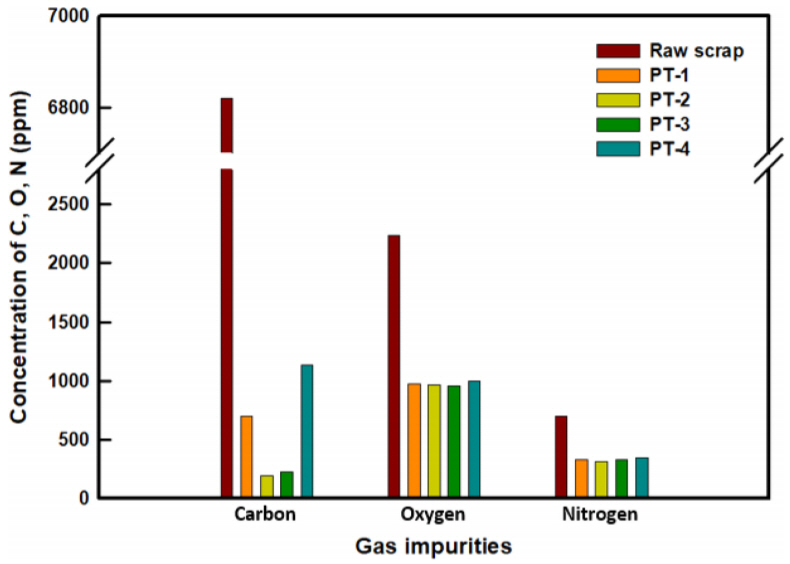
The gas impurities in the Ti scraps before and after pretreatment are shown in Fig 4. The gas impurities were mostly contained in cutting oil adhered on the surface of scraps, otherwise it would be removed by deterioration during processing. The carbon concentration showed the biggest change after pre-treatment, and the Ti-scraps pretreated with PT-2 were the best washed. The amounts of C, O, and N in the raw scraps were 6,820, 2,355, and 705 ppm, respectively. After the pre-treatment with PT-2, these impurities were reduced to 195, 970, and 325 ppm, respectively. The high reductions with PT-2 may be attributed to the fact that the oil on the surface of the scraps was separated better owing to the wettability and contact angle, which in turn, were due to the proper pH value of PT-2.
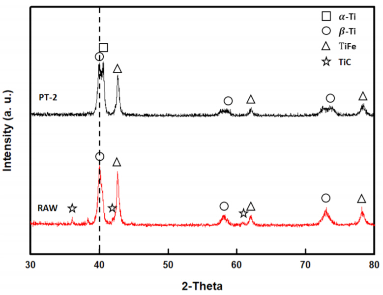
Figure 5 shows the results from the XRD analyses of ferrotitanium ingots prepared with both the Ti raw scraps and the PT-2 scraps. This figure demonstrates the effect of oil on the formation of the ferrotitanium ingots. The ingots were pre-melted with Ti scraps and electrolytic iron at a 7:3 mass ratio. The peaks observed in Fig 5 were mainly ╬▓-Ti, ╬▒-Ti and TiFe. The XRD peaks of PT-2 were divided into two peaks around 40 degrees, which were ╬▓-Ti and ╬▒-Ti. In the case of pre-melting, an ╬▒-Ti peak was observed because electrolytic Fe, which is a ╬▓-Ti stabilizing element, could not contribute to homogenization, due to insufficient melting time. The XRD pattern of the ferrotitanium ingot made of raw scraps showed a TiC peak, which was absent in the ingot made of PT-2 scraps. This difference could be attributed to the large amount of C contained in the oil. When there is a large amount of C in ferrotitanium, its performance as a deoxidizer tends to be poor [11,12].
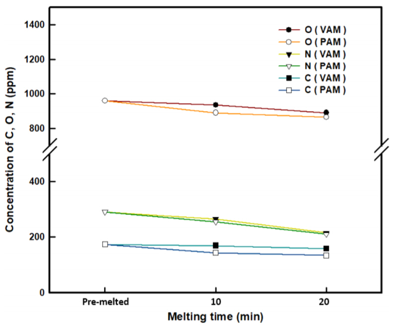
Next, the effect of melting method on ferrotitanium production using the Ti scraps was investigated. The PT-2 scraps, which showed the highest oil removal effect, were used to investigate the change in gas impurities in the ingots prepared by VAM and PAM, as a function of melting time. The variations in C, O, and N with the melting time of the ferrotitanium ingots prepared by the two different melting methods are shown in Fig 6 and Table 3. As the melting time of VAM and PAM was increased, the contents of C, O, and N in the ferrotitanium ingots decreased. However, it was confirmed that the gas impurities in the ferrotitanium ingots melted by PAM, in general, had lower levels of concentration. The removal degree, RD (%) of each gas impurity was defined by the following equation.
where Ci and Cf are the initial and final concentrations. The overall removal degree RDav (%) of the gas impurities is defined as
PAM tends to be slightly higher in RDav (%) than VAM. This is because high energy density could be seen in PAM, owing to the shrinkage nozzle and the orifice gas [30].
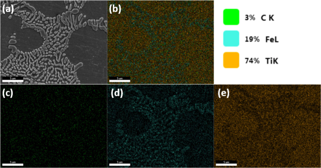
SEM and EDS images of the distribution of Ti, Fe, and C in the ferrotitanium ingot melted by PAM for 20 min are shown in Fig 7. As can be seen from the maps, (d), Fe was distributed in the matrix; however, it was distributed more in the precipitated phase. On the other hand, in image (e), Ti was more distributed in the matrix. This was consistent with the distribution of Fe when the matrix phase was ╬▓-Ti and the precipitation was TiFe. In addition, from the map in (c) it can be confirmed that a carbide phase containing a significant amount of C was not observed.
In this study, the pre-treatment process was optimized by ultrasonic cleaning the oil-stained Ti turning scraps in a low concentration alkaline degreasing solution. Carbide was not observed in the ferrotitanium ingots made of pre-treated scraps obtained from the optimized pre-treatment process, and the ingots revealed a eutectic structure composed of ╬▓-Ti and TiFe. In addition, the ferrotitanium ingot prepared by PAM showed lower concentration of gaseous impurities than that made by VAM.
4. CONCLUSIONS
In this study, Ti turning scraps were cleaned using an optimized pre-treatment process. In the pre-treatment process, ultrasonic cleaning was performed with low alkaline concentration solutions. Ferrotitanium ingots were prepared by VAM and PAM to compare the relative reduction in gaseous impurities. The results obtained can be summarized as follows:
(1) Ultrasonic cleaning of Ti scraps immersed in a low concentration alkaline solution was used to remove the oil on the surface of the Ti turning scraps.
(2) At an appropriate pH, the contact angle increased and the oil became spheroid, and when the pH value was high, the contact angle decreased and became oil wet.
(3) For solutions with higher pH, cleaning efficiency was reduced ŌĆō the roll-up mechanism had a greater effect on cleaning than the solubilization mechanism.
(4) The optimum pretreatment composition for the ultrasonic cleaning of Ti scraps was found to be a 10 g/L TSPP (Na4P2O7) solution with appropriate pH (9.66).
(5) The oil was easily separated from the solution containing TSPP, but the results showed that the removal was better at the proper pH.
(6) After ultrasonic cleaning using the optimum conditions, the removal degrees of C, O, and N gaseous impurities were 97.6%, 58.8%, and 29.2% respectively.
(7) A ferrotitanium ingot of less than 200 ppm carbon was prepared by PAM.