


1. INTRODUCTION
Recently, in the automotive industry, the gas emission standards required by many countries stimulate active research on joining of dissimilar materials [1-5]. The application of light metals such as aluminum has been expanding as such metals are advantageous in terms of weight reduction of a car body. However, the joining of a dissimilar metal pair such as aluminum and steel is problematic due to their vastly different solidus temperature and thermal expansion coefficient, when conventional fusion-based welding technologies are attempted [6,7]. Surface conditions such as corrosion-preventative coating can also act as a barrier against welding [8]. In particular, arc welding and resistance spot welding (RSW), the two techniques that are most commonly used in the automotive industry, have not shown to satisfy the required mechanical properties of structural applications. Lately, a number of other novel dissimilar welding technologies have been developed [7,9], but a reduced cycle time in those methods is necessary for industry implementation. To overcome such issues mechanical joints or fasteners such as self-piercing rivets (SPR) and clinching are used, but their applications are limited due to the thicknesses of the joining materials.
Resistance element welding (REW) is a novel joining technology that can respond to those problems [10,11]. It joins an aluminum (or another dissimilar metal) sheet to a steel sheet using a steel rivet inserted into the aluminum, and the resistance spot welding between the rivet and the steel sheet forms a mechanical interlock to the aluminum. The aluminum does not contribute to formation of complex intermetallic compounds (IMC) as the welding process is limited to the steel components, while the joining can be achieved as rapidly as conventional RSW. Moreover, REW can be easily implemented in the existing manufacturing facilities where RSW is available.
Despite these obvious advantages, the optimization of the REW process is rarely reported in the literature. Ling et al. [10] reported the joining of a A6061 sheet and high-strength boron steel by REW, and found that the lap-shear strength of the REW joint can be nearly seven times that of the RSW joint (Fig 1(a)). As most of the mechanical properties come from the interlock created by the steel rivet, the same method can also be applied to other material combinations that cannot be joined by fusion welding. Manladan et al. [11] reported joining of magnesium and steel using a similar approach (Figure 1(b)). While the two studies above have shown the potential of REW for effective joining of dissimilar metals, a rivet head of a similar thickness as the joining sheet material was used for both studies as shown in Fig 1. The rivet is generally inserted into the aluminum (or magnesium in Fig 1(b)) sheet prior to welding. The use of a large rivet head can also negatively affect the aesthetics of the joint area as well as the subsequent processing steps such as painting.
In this study, we used a newly designed rivet to minimize the portion of the head that sticks out above the aluminum sheet, while still maintaining the mechanical performance. The results show greater possibilities in automotive assembly implementation by joining steel sheets and cast aluminum. The metallurgical features of the joint are revealed using optical and electron microscopy. We also evaluated the effect of misalignment of the electrode and rivet on the mechanical performance by inducing incremental offset tolerances. This study aims to predict and analyze potential defects that may occur during REW.
2. EXPERIMENTAL METHODS
In the present study, a 3 mm thick cast aluminum A365 sheet (provided by Sungwoo Hitech) and a 0.7 mm thick galvannealed mild steel sheet (SGACC provided by Hyundai Steel) were welded by REW. The materials were prepared as 105 čģ 30 mm coupons for welding. The rivet used in the experiment was provided by Arnold Fasteners (Shenyang). The alloy for the rivet was 20MnB4 steel. The chemical composition and mechanical properties of the alloys are provided in Tables 1 and 2, respectively.
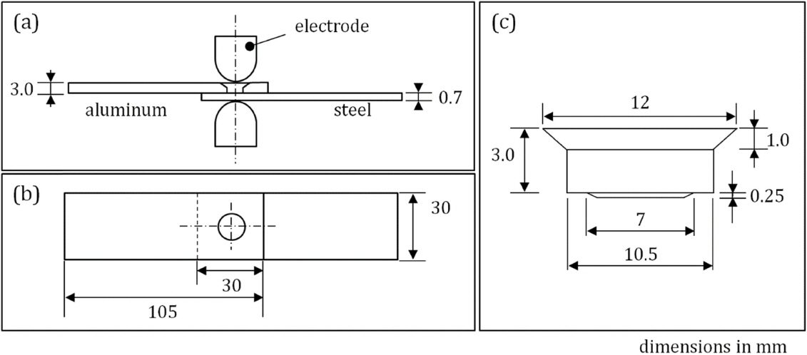
The REW process consists of two parts: rivet insertion and welding. Unlike the previous studies that used a pre-drilled hole [10,11], the newly designed rivet was directly pushed over the aluminum sheet by 30 kN of force so that the rivet was tightly fit without a pre-existing hole. The extruded material was sheared and disposed of. The mechanical test followed the ISO 14273:2016 standard and the coupons were 30 mm overlapped to make a lap-shear configuration. The welding process schematics, location and dimensions of the rivet are provided in Fig 2. In order to simulate the actual manufacturing circumstances, no extra preparation or cleaning was done to the specimens before welding.
The welding process was conducted using a direct-current welding system with a 3 kN force, a 8kA current, and a welding time of 300 ms. The water cooling dome-shaped electrodes were made of a Cu-Cr alloy with a 6 mm radius. The welding experiments were performed in the center of the rivet and subsequent experiments were performed with 2-4 mm offsets to find the influence of misalignment on the weld quality.
For the microstructural analysis the center of the rivet was sectioned along the longitudinal direction of the weld, mounted and polished according to the standard metallographic preparation. The sample was polished up to a 1 ╬╝m diamond paste to observe the microstructure. The mounted sample was then etched using a 2% nital solution for 10s. The analysis was conducted using an optical microscope (Model: Carl Zeiss Axio Imager.A2m) and a scanning electron microscope (Model: Thermofisher Quanta 450). The local hardness of the cross section was also characterized using a micro indenter (model: Future Tech FM-800) with a 100 gf.
The lap-shear tensile test was performed on the REW samples and the results were compared to those of SPR joints with the same material combination. Although REW uses the same principles as conventional RSW, the material combination used in this study (cast aluminum and steel sheet) was not weld-able by RSW due to the creation of excessive intermetallic phases. Instead, the self-piercing riveting (SPR) process was benchmarked as it is one of the most common joining processes of dissimilar metals in automobiles. The SPR samples were provided by Infastech Korea Ltd. A complete drawing of the rivet is not provided in this paper due to a possible conflict of interest but the dimensions of the major components of the rivet are: an outer diameter of 7.75 mm, a distance between legs (inner diameter) of 3.5 mm, and a leg length of 4 mm. The rivet was made from 37MnB4 steel. For the SPR joints, the aluminum sheet was placed underneath the steel sheet to allow penetration and interlocking of the rivet. The SPR process was performed with an insertion speed of 100 mm/s and a force of 58.21 kN. Although the process conditions for the SPR process were not fully optimized, a simple comparison of the mechanical properties with REW provides preliminary information on the mechanical performance and potential applications of both technologies. The lap-shear weld samples were tested using the ZwickRoell Z100 universal tensile testing machine.
3. RESULTS AND DISCUSSION
The results from tensile testing show that the nugget pull-out failure mode is consistently seen as displayed in Fig 3(a). The failure occurred around the nugget in the steel sheet, and because of that the thickness of the aluminum was nearly four times thicker than the steel sheet and the steel microstructure around the nugget was softened by the existence of a heat affected zone (HAZ). The interfacial failure mode was exhibited only when the welding electrode was not properly aligned with the rivet; this type of failure mode is shown in Fig 3(b). The effect of the electrode alignment with the rivet on the weld quality is discussed later.
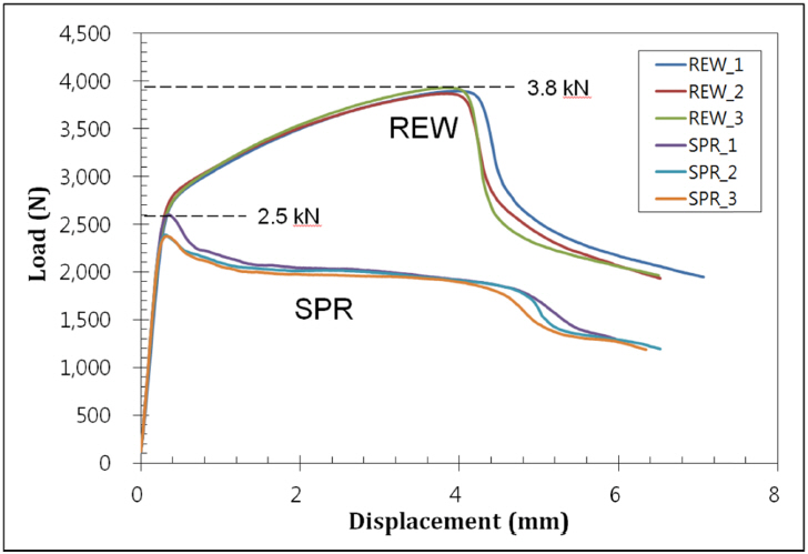
The tensile testing results of the REW and the SPR joints are shown in Figure 4. SPR is currently one of the most common ways of joining dissimilar metals in the automotive industry, for its ease of automation and versatile applications [12]. The test was repeated three times for both methods, and both techniques showed very consistent behavior. The maximum load of the REW samples was about 3.8 kN while for the SPR samples it was about 2.5 kN. A simple comparison between these two numbers needs to consider the joint area of each method, as the diameter of the REW rivet is about 10 mm where the SPR rivet is under 8 mm. Nonetheless, the maximum bearing strength per unit area of the REW is still shown to be equivalent or superior to the SPR joints.
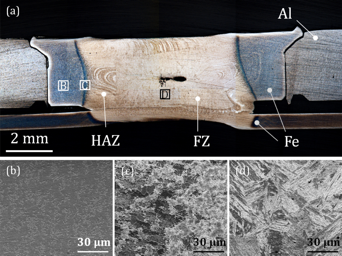
When compared to interfacial failure, the nugget failure mode in RSW generally shows a higher bearing strength because interfacial failure generally occurs when the nugget (fusion zone) involves defects such as solidification cracks or forms excessive martensitic structure which can be brittle. However, nugget failure also indicates existence of a HAZ which is softer than the nugget or the base metal [9] or excessive residual stress around the nugget. Figure 5(a) shows the microstructure of the REW joint. Similarly to a conventional RSW joint, distinctive features indicating metals fusion and HAZ are clearly observed. A number of pores and micro-cracks are observed in the center of the fusion zone, probably because the melting followed by solidification caused shrinkage of the metal [13]. During the solidification of the molten metal, cracks can be formed in a few different locations. Cracks that are formed along the interface where the joining metals meet may act as a path where the cracks propagate. In this case, the existence of the cracks may be detrimental to the mechanical performance of the joint. Cracks from either the top or bottom surface of the joint can also be detrimental, and its formation is also reported to be accelerated with other alloying or coating elements [14]. On the other hand, micro cracks that are formed from the center of the fusion zone may not significantly affect the quality of the weld; the defect free fusion zone and corona bond that surround the void (cracks) can bear more load than the HAZ [15].
A closer micrograph of the FZ is shown in Fig 5(d). The structure mostly consists of needle-shaped martensitic structures which also indicate clear melting and solidification by a high cooling rate. On the other hand, the micrograph taken near the HAZ shows a mixture of ferrite and martensitic phases which make a region that is softer than the nugget. The hardness distribution of the joint is also shown in Figure 6. In this plot, it is clear that the mechanical property (hardness) directly dictates the microstructure and phase distribution mentioned previously. A significant amount of hardening is observed in the nugget and it shows a clear distinction from the HAZ.
Unlike the previous experiments published by Ling et al. [10], the rivet used in this study did not seem to form any metallurgical bonding with the aluminum, so there were also no intermetallic phases. This means that the mechanical performance of REW is mostly, if not all, from the mechanical interlock caused by the steel rivet rather than by the welding to the aluminum sheet.
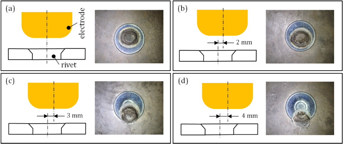
We also investigated effects of electrode misalignment with the rivet. Since the REW process consists of two steps, rivet insertion and welding, there can be a mismatch between the locations of the rivet and the electrode if the tooling is not carefully done. Automation largely helps, but the acceptable tolerance needs to be standardized for the quality management. As shown in Fig.7, the welding process leaves a mark on the top of the rivet (right photograph) after welding, which is due to the joule heating by the contact resistance between the electrode and the rivet, which is more than enough to melt the surfaces. A physical indent is also made by the electrodes.
The size and the geometry of the rivet and electrode significantly affect the misalignment tolerance in REW. For the current rivet design which has a 12 mm diameter on the top side under a 4 mm offset the welding happens within the width of the rivet. Larger offsets can cause arcing of the current through the aluminum sheet, which may prevent formation of a targeted nugget size. Figure 8 shows the nugget size change depending on the electrode offset. The diameter of the nugget was measured to be around 6 mm with less than a 3 mm offset. The change in the size of the nugget was minimal (less than 5%) indicating that almost all of the current passed through the rivet. The nugget size with a 4 mm electrode offset was under 3 mm. Another thing to note in the result is that the offset also causes a rather asymmetrical geometry of the resulting joint, which may not affect the tensile strength but probably causes variations of properties in other configurations, such as cross tension. The 4 mm offset shows a steep decrease of the nugget size and Fig 8(a) shows high porosity in the aluminum indicating melting and possible boiling. Considering the low solidus temperature of aluminum, the result reveals that the path of the current involved the aluminum as well as the rivet.
4. CONCLUSION
This study used a novel welding technology, resistance element welding (REW), to join cast aluminum and mild steel. A newly designed, self-piercing headless rivet was used to simplify the process steps and reduce the cycle time. We found that the mechanical performance of REW on automotive materials was comparable to that of SPR, suggesting that REW can be used in components where SPR cannot be used. The microstructure of the REW joint is similar to that of RSW, revealing microstructure modifications caused by heating and cooling at a high rate. A large offset between the electrode and the rivet caused a radical decrease in the nugget size. The industrial implementation of the process needs to carefully consider the electrode misalignment with the rivet to prevent possible arcing through the material adjacent to the rivet.