Effect of BN Addition on the Mechanical Properties of TiN-BN Composites
Article information
Abstract
Titanium nitride (TiN) has been used extensively in coating materials and cutting tools because of its attractive properties, which include low density, high melting point, high hardness and thermodynamic stability. However, like many ceramic materials, its low fracture toughness limits wide industrial application. The methods generally utilized to improve its fracture toughness involve the fabrication of nanostructured materials and composites. In this paper, BN was evaluated as a reinforcing material in TiN ceramics by pulsed current activated sintering method. Highly dense nanostructured TiN and TiN-BN composites were achieved within 1 min at 1400°C. The effect of BN on the grain size, hardness and fracture toughness of TiN–BN composites was evaluated. The addition of BN to TiN simultaneously improved the hardness and fracture toughness of the TiN-BN composite by refining TiN and the deterrence of crack propagation by BN.
1. INTRODUCTION
Titanium nitride (TiN) has been used extensively in coating materials and cutting tools due to its attractive properties, including low density, high melting point, high hardness, and thermodynamic stability. However, like many ceramic materials, its low fracture toughness limits wide industrial application [1]. The method generally utilized to improve its hardness and fracture toughness involves the fabrication of nanostructured materials and composites. The fracture toughness of a composite can be improved by crack division, deflection and branching [2,3]. Nanostructured materials in particular have received considerable attention as advanced engineering materials with enhanced hardness and toughness [4,5].
TiN nanopowders have recently been fabricated using combustion synthesis, wire explosion, and high energy milling [1,6,7]. Among these methods, high energy milling requires a lower sintering temperature because of the increased reactivity, surface and internal energies, and surface area of the milled powder [7–9]. Even though the initial powder size is less than 50 nm, the grain size increases significantly up to several μm during pulsed current activated sintering [6]. Therefore, deterring grain growth during the sintering process is essential when fabricating nanostructured materials. To effectively sinter nanostructured materials, a second phase such as boron nitride (BN) has been added to deter grain growth during pulsed current activated sintering (PCAS). The method has been demonstrated to be effective for sintering nanostructured materials at low temperature in very short time periods (within 2 minutes) [10–12]. BN is considered to be an ideal second phase for improving fracture toughness [13]. The mechanical properties of BN are comparable to those of graphene. The elastic modulus of BN ranges from 700 to 900 GPa depending on the chirality [13].
The purpose of this study was to fabricate dense and nanostructured TiN-BN composites in a very short time period (< 1 min). The effect of BN on the mechanical properties (hardness and fracture toughness), relative densities, and microstructure of the TiN-BN composites was also investigated.
2. EXPERIMENTAL PROCEDURES
TiN powders with 99.7% purity and a grain size of −400 mesh were supplied by Alfa. BN (Denka. grade GP) with a grain size of < 8 μm was used as the additive. Powders of four compositions corresponding to TiN, TiN-1vol% BN, TiN-3vol% BN and TiN-5vol% BN were prepared by weighing and then high-energy ball milling for 10 h at 250 rpm. WC-Co balls with a 10 mm diameter were used as media in a sealed cylindrical vial under an argon atmosphere.
The milled powders were used to fill a graphite die and then introduced into the pulsed current activated sintering (PCAS) system. A schematic diagram of the system is displayed in Ref. [14]. The PCAS apparatus has a 30 kW power supply which provides a pulsed current through the die and powder, and a 60 kN uniaxial press. The system was evacuated and a uniaxial pressure of 70 MPa was applied to the powders. A pulsed current was then applied and maintained until the consolidation rate was negligible. Specimen shrinkage was measured in real time using a linear gauge measuring vertical displacement. Temperature was measured by a pyrometer focused on the surface of the graphite die. The heating rates were approximately 1500°K per minute during the process. At the end of the process, the pulsed current was turned off and the specimen allowed to cool to room temperature.
The relative density of the sintered specimen was measured by the Archimedes method. Microstructure was investigated based on the fracture surface of the sintered samples. Compositional, microstructural and phase analyses of the samples was carried out using X-ray diffraction (XRD) with a Cu target, and FE-SEM with energy dispersive X-ray spectroscopy (EDS). Vickers hardness was measured using performing indentations at a load of 10 kgf. The grain size of the TiN was evaluated from the full width at half-maximum of the diffraction peak using Suryanarayana and Grant Norton's formula [15].
3. RESULTS AND DISCUSSION
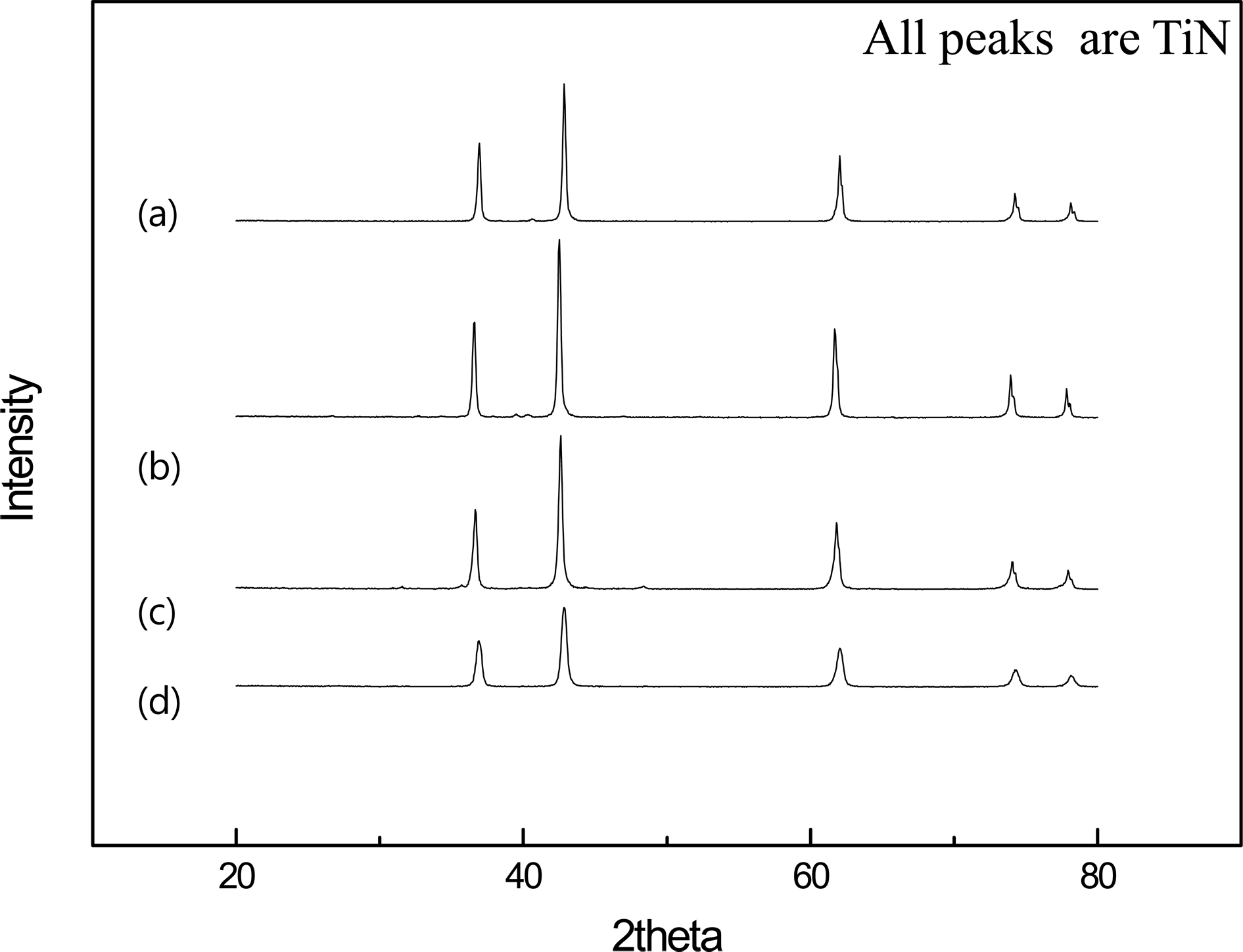
Figure 1 displays the XRD patterns of the raw powders of TiN and BN, and Fig. 2 shows the XRD patterns of the TiN, TiN-1vol% BN, TiN-3vol% BN and TiN-5vol% BN powders after milling. The broadening of the TiN peaks compared to the other powders shown in Fig. 1 is due to the induced strain and crystallite refinement during the milling process. The TiN particle size was calculated from a plot of Br cosθ versus sinθ in Grant Norton's formula [15]. The average grain sizes of the TiN in TiN, TiN-1 vol% BN, TiN-3vol% BN, and TiN-5vol% BN powders were determined to be about 17, 13, 17 and 19 nm, respectively. Figure 3 displays the FE-SEM image and EDS of TiN-5vol% BN powders after milling for 10 h. The powders consist of nanopowders and show some agglomeration of very fine particles. In EDS, only Ti, B N, and Pt peaks are detected. The Pt peak comes from the coating applied to clearly observe the microstructure. The impurity peaks of W and Fe that are usually introduced during the ball milling from the ball and container could not be detected.
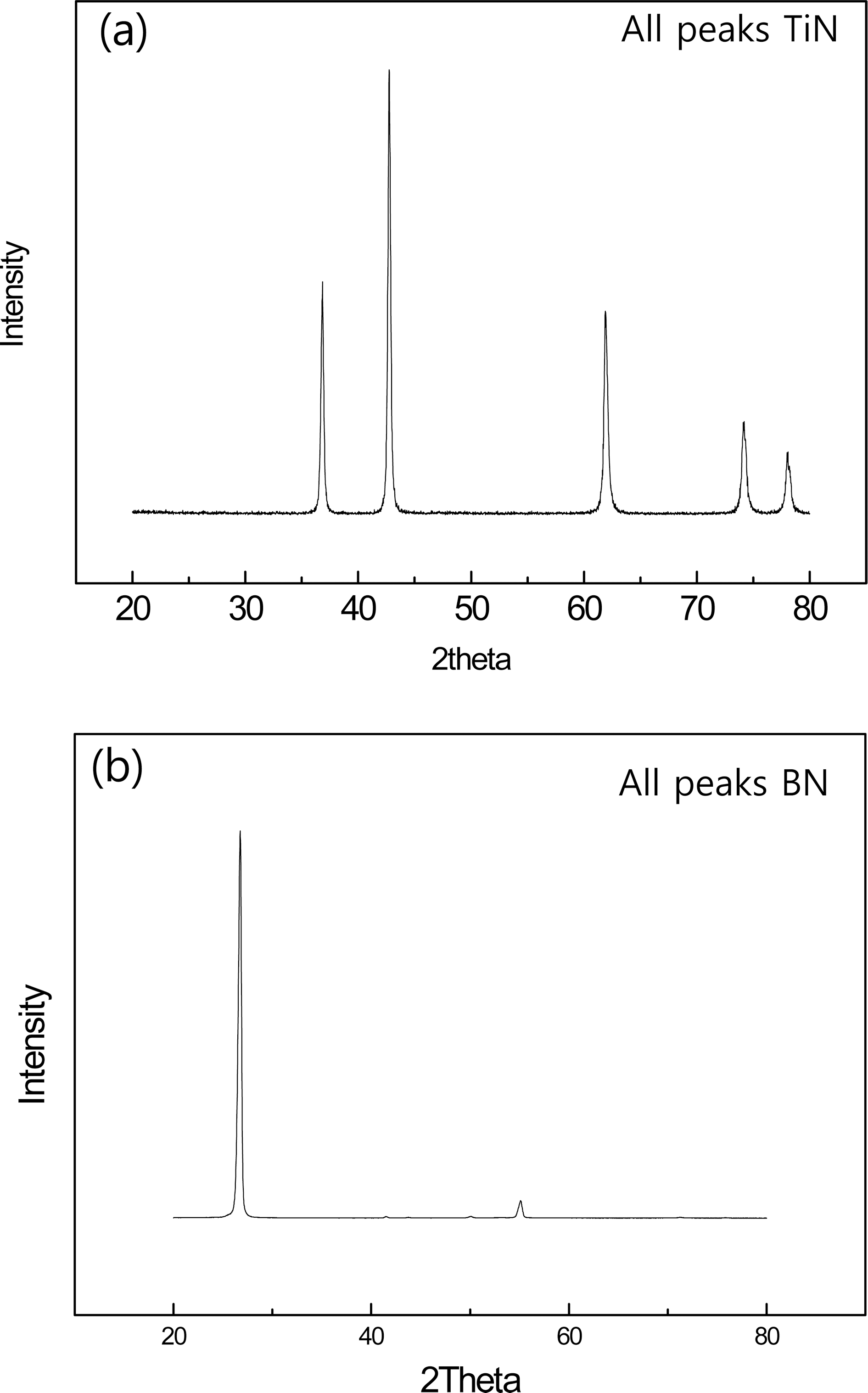
XRD patterns of raw powder: (a) TiN, (b) BN.

XRD patterns of TiN powder + × vol% BN powder milled for 10 h: (a) x=0 (b) x=1 (c) x=3 and (d) x=5.

FE-SEM image and EDS of TiN powder + 5 vol% BN powder milled for 10h.
The shrinkage displacement with heating temperature curve provides useful information on the consolidation behavior. Figure 4 displays the shrinkage records of the TiN, TiN-1vol% BN, TiN-3vol% BN, and TiN-5vol% BN compacts. Thermal expansion occurs in all the samples up to a heating time of 5 s. Subsequently, shrinkage displacement rapidly increases to 1400°C, at which the sintering terminates. The shrinkage curve indicates that the consolidation terminates within one minute.

Variations of shrinkage displacement and temperature with heating time during the sintering of TiN and TiN-BN samples by PCAS.
The XRD patterns of TiN, TiN-1vol% BN, TiN-3vol% BN, and TiN-5vol% BN after sintering are shown in Fig. 5. In all cases, only the TiN peaks were detected. Their grain sizes were evaluated using the plot of Brcosθ versus sinθ in Suryanarayana's equation [15], as shown in Fig. 6. The average grain sizes of TiN were about 110, 90, 77, and 45 nm for TiN, TiN-1 vol% BN, TiN-3vol% BN and TiN-5vol% BN, respectively. This indicates that the grain size of TiN decreases as the BN content increases. This means that BN may deter the grain growth of TiN during sintering. Figure 7 displays SEM images of the fracture surfaces of the samples after sintering at 1400°C. The grain refining effect of BN can also be confirmed by the fracture surface. It can be seen that the crack propagation mode in all samples was intergranular as the cracks propagate through grain boundaries.
XRD patterns of TiN + × vol% BN specimens sintered at 1400°C: (a) x=0, (b) x=1, (c) x=3 and (d) x=5.

Plot of Br cosθ versus sinθ for TiN in TiN + × vol% BN specimens sintered at 1400°C: (a) x=0 (b) x=1 (c) x=3 and (d) x=5.
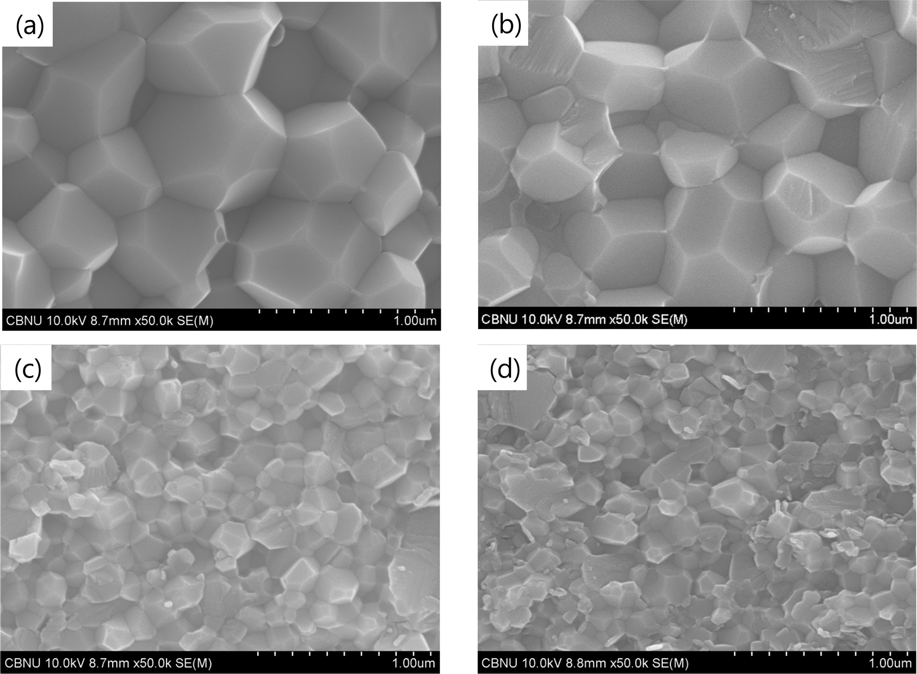
FE-SEM images of fracture surface of TiN + × vol% BN specimens sintered at 1400°C: (a) x=0, (b) x=1, (c) x=3 and (d) x=5.
It should be mentioned that nano structured TiN can be achieved by pulsed current activated sintering even for pure TiN without BN. This retention of ultra-fine grain structure can be attributed to sintering for a short period at low temperature. The composites were dense and relative densities of 100, 97, 100, and 99% were achieved for TiN, TiN-1vol% BN, TiN-3vol% BN, and TiN-5vol% BN, respectively. It was clearly demonstrated that pulsed current activated sintering is effective for sintering nanostructured TiN and TiN-BN composites. The effects of pulsed current on enhanced sintering have been reported to be the product of plasma in pores, the rapid heating due to Joule heat at the contact points of powders, and rapid mass transport because of electromigration [16,17].
Several investigators have studied the consolidation of TiN using spark plasma sintering. TiN with 98% relative density and 10 μm grain size can be obtained by sintering at 1800°C for 20 min [1]. Kim et al. [6] reported that even though the initial particle size of TiN was about 25 nm, the grain size increased significantly up to 7.1 μm during sintering at 1600°C. Compared with the above studies, nanostructured TiN with higher density can be achieved within a shorter time using mechanically milled powder TiN and a pulsed current activated sintering method. Mechanical milling is understood to improve consolidation by increasing internal and surface energies, providing a diffusion route at contact points, and increasing the surface area of the milled powder [7–9].
Vickers hardness was measured on the polished sections of the TiN, TiN-1 vol% BN, TiN-3vol% BN, and TiN-5vol% BN samples using a 10 kgf load. Indentations with 10kgf load produced cracks around the indentation, from which fracture toughness can be evaluated. The lengths of these cracks permit calculation of the fracture toughness values according to the equation by Niihara et al. [18]. The fracture toughness and hardness values of the TiN sample were 3.5 MPa·m1/2 and 870 kg/mm2, those of the TiN-1 vol% BN sample were 1588 kg/mm2 and 4.6 MPa·m1/2, those of the TiN-3vol% BN sample were 1746 kg/mm2 and 4.7 MPa ·m1/2, and those of the TiN-5vol% BN sample were 1654 kg/mm2 and 4.5 MPa·m1/2, respectively. The results indicate that both hardness and fracture toughness increased simultaneously with the addition of BN. To understand the effect of BN on the mechanical properties of the TiN-BN composites, two factors may be considered: the effect of TiN on grain refinement and the effect of BN on crack propagation, which affects toughness. Hardness generally increases with grain refinement according to the Hall-Petch type strengthening effect. In this study the addition of BN significantly refined the grain size of TiN. Figure 8 displays the Vickers hardness indentations in the TiN, TiN-1 vol% BN, TiN-3vol% BN and TiN-5vol% BN samples. They show typical cracks propagating radially from the indentation corner. The toughness of the TiN-BN composite may be because the BN deters crack propagation. The effect of BN on the fracture toughness of the Si3N4-BN composites was investigated [19]. The fracture toughness of the composite increased with the addition of BN due to crack branching, crack deflection and crack bridging. In this study, crack branching (↓) and crack deflection (↑) were observed, as shown in Fig. 9. The enhancement in the fracture toughness of the TiN-BN composite is believed to be due to the BN, which may deter crack propagation in the composite.

Vickers hardness indentation in TiN + × vol% BN specimens sintered at 1400°C: (a) x=0 (b) x=1 (c) x=3 and (d) x=5.

Crack propagation in TiN + 5 vol% BN composite sintered at 1400°C.
4. CONCLUSIONS
Nanopowders of TiN were made using high-energy ball milling. Nanostructured TiN and TiN-BN composites with near full-density could be obtained within 1 min. It was demonstrated that nanostructured TiN with higher density can be achieved within a shorter time at a lower temperature by using mechanically milled powder and a pulsed current activated sintering method. The grain size of TiN was reduced significantly by the addition of BN. The hardness and the fracture toughness values of the TiN sample were 870 kg/mm2 and 3.5 MPa·m1/2, those of the TiN-1 vol% BN sample were 1588 kg/mm2 and 4.6 MPa·m1/2, those of the TiN-3vol% BN sample were 1746 kg/mm2 and 4.7 MPa·m1/2, and those of the TiN-5vol% BN sample are 1654 kg/mm2 and 4.5 MPa·m1/2, respectively. The addition of BN to TiN simultaneously improved the hardness and fracture toughness of the TiN-BN composite by refining the TiN and the deterrence of crack propagation by BN. This study demonstrates that BN can be an effective reinforcing material to improve the fracture toughness and hardness of TiN composites.
ACKNOWLEDGEMENTS
This research was supported by Basic Science Research Program though the National Research Foundation of Korea (NRF) funded by the Ministry of Education (2015R1D1A1A01056600) and this work was supported by the Korea Institute of Energy Technology Evaluation and Planning (KETEP) and the Ministry of Trade, Industry & Energy (MOTIE) of the Republic of Korea (No. 20184030202210) And following are results of a study on the “Leaders in Industry-university Cooperation +” Project, supported by the Ministry of Education and National Research Foundation of Korea.